基于 Metal 的 ARKit 使用指南(上)

- 原文地址:Using ARKit with Metal
- 原文作者:Marius Horga
- 译文出自:掘金翻译计划
- 本文永久链接:https://github.com/xitu/gold-miner/blob/master/TODO/using-arkit-with-metal.md
- 译者:RichardLeeH
- 校对者:Danny1451
增强现实提供了一种将虚拟内容渲染到通过移动设备摄像头捕获的真实世界场景之上的方法。上个月,在 WWDC 2017 上,我们都非常兴奋地看到了 苹果 的新 ARKit 高级 API 框架,它运行于搭载 A9 处理器或更高配置的 iOS 11 设备上。我们看到的一些 ARKit 实验已相当出色,比如下面这个:
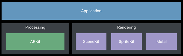
一个 ARKit 应用中包含 3 种不同的层:
- 追踪层 - 不需要额外的配置就可以采用视觉惯性定位追踪场景。
- 场景理解层 - 利用平面检测,点击检测和光照估计来检测场景属性的能力。
- 渲染层 - 由于 SpriteKit 和 SceneKit 提供的模板 AR 视图,因此可以轻松集成,也可以使用
Metal自定义视图。所有的预渲染处理都是由 ARKit 完成的,它还负责使用 AVFoundation 和 CoreMotion 捕获图像。
在本系列的第一部分中,我们将主要关注 Metal 下的 渲染,并在本系列的下一部分讨论其他两个部分。在一个 AR 应用中,追踪层 和 场景理解层 完全由 ARKit 框架处理,而 渲染层 由 SpriteKit、SceneKit 或 Metal 处理:

开始之前,我们需要通过一个 ARSessionConfiguration 对象创建一个 ARSession 实例,接着我们在这个配置上调用 run() 方法。ARSession 同时会依赖 AVCaptureSession 和 CMMotionManager 运行对象来获取追踪的图像和运动数据。最后,ARSession 将会输出当前 frame 到一个 ARFrame 对象。
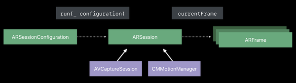

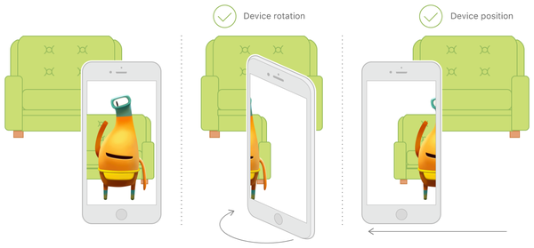
ARSessionConfiguration 对象包含了会话将会使用的追踪类型信息。 ARSessionConfiguration 基础配置类提供了 3 个自由度的运动追踪 (设备 方向) 而其子类 ARWorldTrackingSessionConfiguration,提供了 6 个自由度的运动追踪 (设备 位置 和 方向)。

当设备不支持真实场景追踪时,它会采用基本配置:
if ARWorldTrackingSessionConfiguration.isSupported {
    configuration = ARWorldTrackingSessionConfiguration()
} else {
    configuration = ARSessionConfiguration()
}
ARFrame 包含捕获的图像,跟踪信息以及通过 ARAnchor 对象获取的场景信息,,**ARAnchor ** 对象包含有关真实世界位置和方向的信息,并且可以轻松地添加,更新或从会话中删除。跟踪是实时确定物理位置的能力。 然而,世界追踪决定了位置和方向,它与物理距离一起工作,相对于起始位置并提供3D特征点。
ARFrame 的最后一个组件是 ARCamera 对象,它便于转换(平移,旋转,缩放),并且包含了跟踪的状态和相机的相关方法。跟踪质量在很大程度上依赖于不间断的传感器数据,静态场景,并且在场景纹理复杂的环境中更加准确。跟踪状态有三个值:不可用(摄像机只有单位矩阵),限制(场景功能不足或不够静态)和 正常(摄像机被填充数据)。 会话中断是由于相机输入不可用或停止跟踪造成的:
func session(_ session: ARSession, cameraDidChangeTrackingState camera: ARCamera) {
    if case .limited(let reason) = camera.trackingState {
        // Notify user of limited tracking state
    }
}
func sessionWasInterrupted(_ session: ARSession) {
    showOverlay()
}
func sessionInterruptionEnded(_ session: ARSession) {
    hideOverlay()
    // Optionally restart experience
}
在 SceneKit 中使用 ARSCNView 的代理进行渲染,包括添加,更新或者删除节点。类似的,SpriteKit 使用 ARSKView 的代理将SKNodes 映射为 ARAnchor 对象。由于 SpriteKit 为 2D,因此它不能使用真实世界的摄像头位置,所以它将锚点的位置投影到 ARSKView,并在投影的位置上将精灵渲染为一个广告牌(平面),所以精灵会一直面对着摄像头。对于 Metal,没有自定义的 AR 视图,所以重任就落在了程序员手里。为了处理渲染的图像,我们需要:
- 绘制背景摄像机图像 (从像素缓冲区生成一个纹理)
- 更新虚拟摄像头
- 更新光照
- 更新几何图形的变换
所有这些信息都在 ARFrame 对象中。获取 frame,有两种方式:轮询或使用代理。我们将简单介绍后者。我使用了 Metal 的 ARKit 模板,把它精简到最小,这样我就能更好地理解它是如何工作的。我做的第一件事是移除所有的 C 依赖,这样就不需要桥接。它在以后会很有用,因为类型和枚举常量可以在 API 代码和着色器之间共享,但这篇文章的目的并不需要。
接着,回到 ViewController 上,它需要作为 MTKView 和 ARSession 的代理。我们创建一个 Renderer 实例,用于同代理一起实时更新应用:
var session: ARSession!
var renderer: Renderer!

override func viewDidLoad() {
    super.viewDidLoad()
    session = ARSession()
    session.delegate = self
    if let view = self.view as? MTKView {
        view.device = MTLCreateSystemDefaultDevice()
        view.delegate = self
        renderer = Renderer(session: session, metalDevice: view.device!, renderDestination: view)
        renderer.drawRectResized(size: view.bounds.size)
    }
    let tapGesture = UITapGestureRecognizer(target: self, action: #selector(self.handleTap(gestureRecognize:)))
    view.addGestureRecognizer(tapGesture)
}
正如你所看到的,我们还添加了一个手势识别,用于在场景中添加虚拟内容。首先,我们获取会话的当前帧,接着创建一个变换将我们的实体放到摄像头前(本例中 0.3 米),最后使用这个变换在会话中添加一个新的锚点。
func handleTap(gestureRecognize: UITapGestureRecognizer) {
    if let currentFrame = session.currentFrame {
        var translation = matrix_identity_float4x4
        translation.columns.3.z = -0.3
        let transform = simd_mul(currentFrame.camera.transform, translation)
        let anchor = ARAnchor(transform: transform)
        session.add(anchor: anchor)
    }
}
我们分别使用 viewWillAppear() 和 viewWillDisappear() 方法启动和暂停会话:
override func viewWillAppear(_ animated: Bool) {
    super.viewWillAppear(animated)
    let configuration = ARWorldTrackingSessionConfiguration()
    session.run(configuration)
}

override func viewWillDisappear(_ animated: Bool) {
    super.viewWillDisappear(animated)
    session.pause()
}
剩下的就是我们需要实现视图更新、会话错误和中断的代理方法:
func mtkView(_ view: MTKView, drawableSizeWillChange size: CGSize) {
    renderer.drawRectResized(size: size)
}

func draw(in view: MTKView) {
    renderer.update()
}

func session(_ session: ARSession, didFailWithError error: Error) {}

func sessionWasInterrupted(_ session: ARSession) {}

func sessionInterruptionEnded(_ session: ARSession) {}
打开 Renderer.swift 文件。要注意的第一件事是使用一个非常方便的协议,它可以让我们访问所有的 MTKView属性:
protocol RenderDestinationProvider {
    var currentRenderPassDescriptor: MTLRenderPassDescriptor? { get }
    var currentDrawable: CAMetalDrawable? { get }
    var colorPixelFormat: MTLPixelFormat { get set }
    var depthStencilPixelFormat: MTLPixelFormat { get set }
    var sampleCount: Int { get set }
}
现在我们可以扩展 MTKView 类(在 ViewController中),以便其遵守这个协议:
extension MTKView : RenderDestinationProvider {}
Renderer 类的高级视图,以下为伪代码:
init() {
    setupPipeline()
    setupAssets()
}

func update() {
    updateBufferStates()
    updateSharedUniforms()
    updateAnchors()
    updateCapturedImageTextures()
    updateImagePlane()
    drawCapturedImage()
    drawAnchorGeometry()
}
和往常一样,我们首先使用 setupPipeline() 函数设置管道。 然后,在 **setupAssets()**中,我们创建了模型,每当我们使用我们的单击手势时,模型将被加载。 MTKView 委托将调用 update() 函数获取所需更新并绘制。 我们详细介绍他们。 首先我们看看 updateBufferStates(),它更新我们写入当前帧的缓冲区的位置(本实例中,我们使用一个 3 个槽的环形缓冲区):
func updateBufferStates() {
    uniformBufferIndex = (uniformBufferIndex + 1) % maxBuffersInFlight
    sharedUniformBufferOffset = alignedSharedUniformSize * uniformBufferIndex
    anchorUniformBufferOffset = alignedInstanceUniformSize * uniformBufferIndex
    sharedUniformBufferAddress = sharedUniformBuffer.contents().advanced(by: sharedUniformBufferOffset)
    anchorUniformBufferAddress = anchorUniformBuffer.contents().advanced(by: anchorUniformBufferOffset)
}
在 updateSharedUniforms() 方法中,我们更新 frame 的共享 uniform 变量并设置场景的光照:
func updateSharedUniforms(frame: ARFrame) {
    let uniforms = sharedUniformBufferAddress.assumingMemoryBound(to: SharedUniforms.self)
    uniforms.pointee.viewMatrix = simd_inverse(frame.camera.transform)
    uniforms.pointee.projectionMatrix = frame.camera.projectionMatrix(withViewportSize: viewportSize, orientation: .landscapeRight, zNear: 0.001, zFar: 1000)
    var ambientIntensity: Float = 1.0
    if let lightEstimate = frame.lightEstimate {
        ambientIntensity = Float(lightEstimate.ambientIntensity) / 1000.0
    }
    let ambientLightColor: vector_float3 = vector3(0.5, 0.5, 0.5)
    uniforms.pointee.ambientLightColor = ambientLightColor * ambientIntensity
    var directionalLightDirection : vector_float3 = vector3(0.0, 0.0, -1.0)
    directionalLightDirection = simd_normalize(directionalLightDirection)
    uniforms.pointee.directionalLightDirection = directionalLightDirection
    let directionalLightColor: vector_float3 = vector3(0.6, 0.6, 0.6)
    uniforms.pointee.directionalLightColor = directionalLightColor * ambientIntensity
    uniforms.pointee.materialShininess = 30
}
在 updateAnchors() 方法中,我们用当前 frame 的锚点的变换来更新锚定元素缓冲区:
func updateAnchors(frame: ARFrame) {
    anchorInstanceCount = min(frame.anchors.count, maxAnchorInstanceCount)
    var anchorOffset: Int = 0
    if anchorInstanceCount == maxAnchorInstanceCount {
        anchorOffset = max(frame.anchors.count - maxAnchorInstanceCount, 0)
    }
    for index in 0..<anchorInstanceCount {
        let anchor = frame.anchors[index + anchorOffset]
        var coordinateSpaceTransform = matrix_identity_float4x4
        coordinateSpaceTransform.columns.2.z = -1.0
        let modelMatrix = simd_mul(anchor.transform, coordinateSpaceTransform)
        let anchorUniforms = anchorUniformBufferAddress.assumingMemoryBound(to: InstanceUniforms.self).advanced(by: index)
        anchorUniforms.pointee.modelMatrix = modelMatrix
    }
}
在 updateCapturedImageTextures() 方法中,我们从提供的帧捕获的图像中创建两个纹理:
func updateCapturedImageTextures(frame: ARFrame) {
    let pixelBuffer = frame.capturedImage
    if (CVPixelBufferGetPlaneCount(pixelBuffer) < 2) { return }
    capturedImageTextureY = createTexture(fromPixelBuffer: pixelBuffer, pixelFormat:.r8Unorm, planeIndex:0)!
    capturedImageTextureCbCr = createTexture(fromPixelBuffer: pixelBuffer, pixelFormat:.rg8Unorm, planeIndex:1)!
}
在 updateImagePlane() 方法中,我们更新图像屏幕的纹理坐标,让它能够保持比例并填满整个视图:
func updateImagePlane(frame: ARFrame) {
    let displayToCameraTransform = frame.displayTransform(withViewportSize: viewportSize, orientation: .landscapeRight).inverted()
    let vertexData = imagePlaneVertexBuffer.contents().assumingMemoryBound(to: Float.self)
    for index in 0...3 {
        let textureCoordIndex = 4 * index + 2
        let textureCoord = CGPoint(x: CGFloat(planeVertexData[textureCoordIndex]), y: CGFloat(planeVertexData[textureCoordIndex + 1]))
        let transformedCoord = textureCoord.applying(displayToCameraTransform)
        vertexData[textureCoordIndex] = Float(transformedCoord.x)
        vertexData[textureCoordIndex + 1] = Float(transformedCoord.y)
    }
}
在 drawCapturedImage() 方法中,我们在场景中绘制摄像头:
func drawCapturedImage(renderEncoder: MTLRenderCommandEncoder) {
    guard capturedImageTextureY != nil && capturedImageTextureCbCr != nil else { return }
    renderEncoder.pushDebugGroup("DrawCapturedImage")
    renderEncoder.setCullMode(.none)
    renderEncoder.setRenderPipelineState(capturedImagePipelineState)
    renderEncoder.setDepthStencilState(capturedImageDepthState)
    renderEncoder.setVertexBuffer(imagePlaneVertexBuffer, offset: 0, index: 0)
    renderEncoder.setFragmentTexture(capturedImageTextureY, index: 1)
    renderEncoder.setFragmentTexture(capturedImageTextureCbCr, index: 2)
    renderEncoder.drawPrimitives(type: .triangleStrip, vertexStart: 0, vertexCount: 4)
    renderEncoder.popDebugGroup()
}
最后,在 drawAnchorGeometry() 中为我们创建的虚拟内容绘制锚点:
func drawAnchorGeometry(renderEncoder: MTLRenderCommandEncoder) {
    guard anchorInstanceCount > 0 else { return }
    renderEncoder.pushDebugGroup("DrawAnchors")
    renderEncoder.setCullMode(.back)
    renderEncoder.setRenderPipelineState(anchorPipelineState)
    renderEncoder.setDepthStencilState(anchorDepthState)
    renderEncoder.setVertexBuffer(anchorUniformBuffer, offset: anchorUniformBufferOffset, index: 2)
    renderEncoder.setVertexBuffer(sharedUniformBuffer, offset: sharedUniformBufferOffset, index: 3)
    renderEncoder.setFragmentBuffer(sharedUniformBuffer, offset: sharedUniformBufferOffset, index: 3)
    for bufferIndex in 0..<mesh.vertexBuffers.count {
        let vertexBuffer = mesh.vertexBuffers[bufferIndex]
        renderEncoder.setVertexBuffer(vertexBuffer.buffer, offset: vertexBuffer.offset, index:bufferIndex)
    }
    for submesh in mesh.submeshes {
        renderEncoder.drawIndexedPrimitives(type: submesh.primitiveType, indexCount: submesh.indexCount, indexType: submesh.indexType, indexBuffer: submesh.indexBuffer.buffer, indexBufferOffset: submesh.indexBuffer.offset, instanceCount: anchorInstanceCount)
    }
    renderEncoder.popDebugGroup()
}
回到我们前面简要提到的 setupPipeline() 方法。我们创建两个渲染管道状态的对象,一个用于捕获的图像(摄像头) ,另一个用于在场景中放置虚拟对象时创建的锚点。正如预期的那样,每个状态对象都有自己的一对顶点和片段函数 - 它把我们带到我们需要查看的最后一个文件 -Shaders.metal 文件。在第一对被捕获图像的着色部分,在顶点着色器中,我们传入图像的顶点位置和纹理坐标参数:
vertex ImageColorInOut capturedImageVertexTransform(ImageVertex in [[stage_in]]) {
    ImageColorInOut out;
    out.position = float4(in.position, 0.0, 1.0);
    out.texCoord = in.texCoord;
    return out;
}
在片段着色器中,我们对两个纹理进行采样,得到给定纹理坐标下的颜色,然后返回转换后的 RGB 颜色:
fragment float4 capturedImageFragmentShader(ImageColorInOut in [[stage_in]],
                                            texture2d<float, access::sample> textureY [[ texture(1) ]],
                                            texture2d<float, access::sample> textureCbCr [[ texture(2) ]]) {
    constexpr sampler colorSampler(mip_filter::linear, mag_filter::linear, min_filter::linear);
    const float4x4 ycbcrToRGBTransform = float4x4(float4(+1.0000f, +1.0000f, +1.0000f, +0.0000f),
                                                  float4(+0.0000f, -0.3441f, +1.7720f, +0.0000f),
                                                  float4(+1.4020f, -0.7141f, +0.0000f, +0.0000f),
                                                  float4(-0.7010f, +0.5291f, -0.8860f, +1.0000f));
    float4 ycbcr = float4(textureY.sample(colorSampler, in.texCoord).r, textureCbCr.sample(colorSampler, in.texCoord).rg, 1.0);
    return ycbcrToRGBTransform * ycbcr;
}
对于第二个几何锚点的着色器,在顶点着色器中,我们计算我们顶点在剪辑空间中的位置,并输出剪裁和光栅化,然后为每个面着色不同的颜色,然后计算观察坐标空间中顶点的位置,最后将我们的坐标系转换到世界坐标系:
vertex ColorInOut anchorGeometryVertexTransform(Vertex in [[stage_in]],
                                                constant SharedUniforms &sharedUniforms [[ buffer(3) ]],
                                                constant InstanceUniforms *instanceUniforms [[ buffer(2) ]],
                                                ushort vid [[vertex_id]],
                                                ushort iid [[instance_id]]) {
    ColorInOut out;
    float4 position = float4(in.position, 1.0);
    float4x4 modelMatrix = instanceUniforms[iid].modelMatrix;
    float4x4 modelViewMatrix = sharedUniforms.viewMatrix * modelMatrix;
    out.position = sharedUniforms.projectionMatrix * modelViewMatrix * position;
    ushort colorID = vid / 4 % 6;
    out.color = colorID == 0 ? float4(0.0, 1.0, 0.0, 1.0)  // Right face
              : colorID == 1 ? float4(1.0, 0.0, 0.0, 1.0)  // Left face
              : colorID == 2 ? float4(0.0, 0.0, 1.0, 1.0)  // Top face
              : colorID == 3 ? float4(1.0, 0.5, 0.0, 1.0)  // Bottom face
              : colorID == 4 ? float4(1.0, 1.0, 0.0, 1.0)  // Back face
              :                float4(1.0, 1.0, 1.0, 1.0); // Front face
    out.eyePosition = half3((modelViewMatrix * position).xyz);
    float4 normal = modelMatrix * float4(in.normal.x, in.normal.y, in.normal.z, 0.0f);
    out.normal = normalize(half3(normal.xyz));
    return out;
}
在片段着色器中,我们计算定向光的贡献作为漫反射和镜面反射项的总和,然后我们通过将颜色映射的采样乘以片段的光照值来计算最终的颜色,最后我们用刚刚计算出来的颜色和颜色映射的 alpha 通道的值作为该片段的 alpha 的值:
fragment float4 anchorGeometryFragmentLighting(ColorInOut in [[stage_in]],
                                               constant SharedUniforms &uniforms [[ buffer(3) ]]) {
    float3 normal = float3(in.normal);
    float3 directionalContribution = float3(0);
    {
        float nDotL = saturate(dot(normal, -uniforms.directionalLightDirection));
        float3 diffuseTerm = uniforms.directionalLightColor * nDotL;
        float3 halfwayVector = normalize(-uniforms.directionalLightDirection - float3(in.eyePosition));
        float reflectionAngle = saturate(dot(normal, halfwayVector));
        float specularIntensity = saturate(powr(reflectionAngle, uniforms.materialShininess));
        float3 specularTerm = uniforms.directionalLightColor * specularIntensity;
        directionalContribution = diffuseTerm + specularTerm;
    }
    float3 ambientContribution = uniforms.ambientLightColor;
    float3 lightContributions = ambientContribution + directionalContribution;
    float3 color = in.color.rgb * lightContributions;
    return float4(color, in.color.w);
}
如果你运行这个程序,你就可以点击屏幕并在实时摄像头视图中添加立方体,然后移动或靠近这些立方体观察每个面的不同颜色,就像这样:
在本系列的下一部分,我们将会更深入的研究 追踪层 和 场景解析层 并了解并了解平面检测,撞击测试,碰撞和物理效果如何使我们的体验更加丰富。 源代码 已经发布到 GitHub。
下次见!
掘金翻译计划 是一个翻译优质互联网技术文章的社区,文章来源为 掘金 上的英文分享文章。内容覆盖 Android、iOS、React、前端、后端、产品、设计 等领域,想要查看更多优质译文请持续关注 掘金翻译计划、官方微博、知乎专栏。